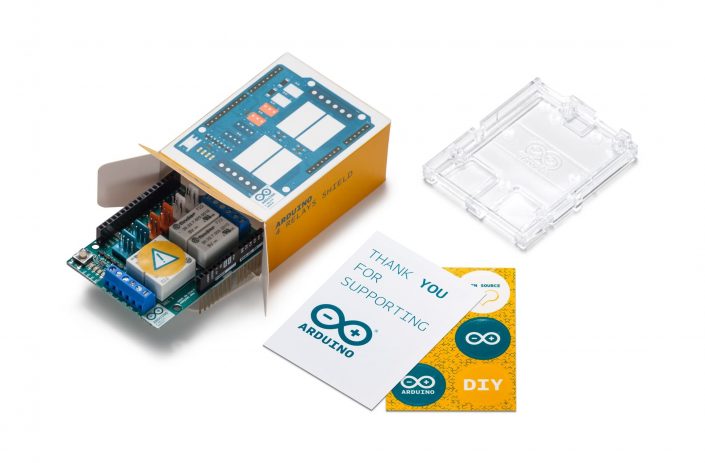
Official ARDUINO 4 RELAYS SHIELD
- үнэ: 98,000 төг
Code: A000110-R
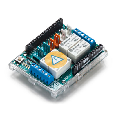
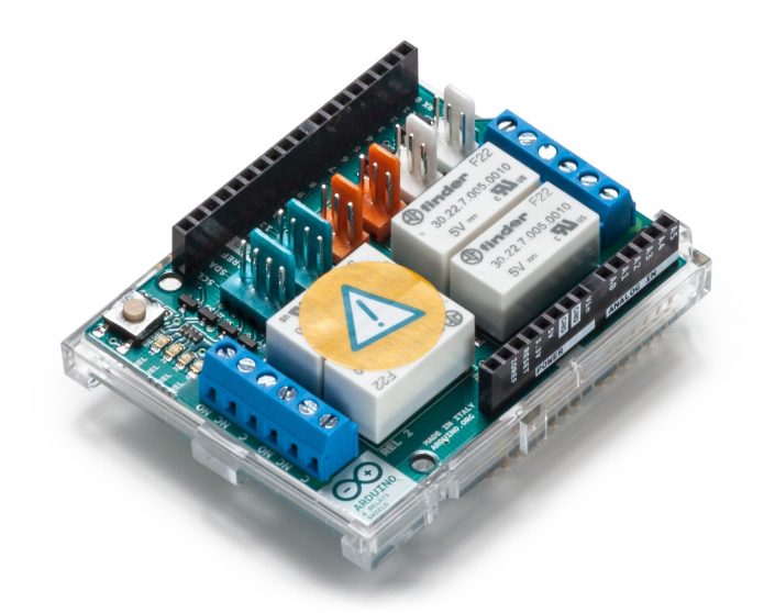
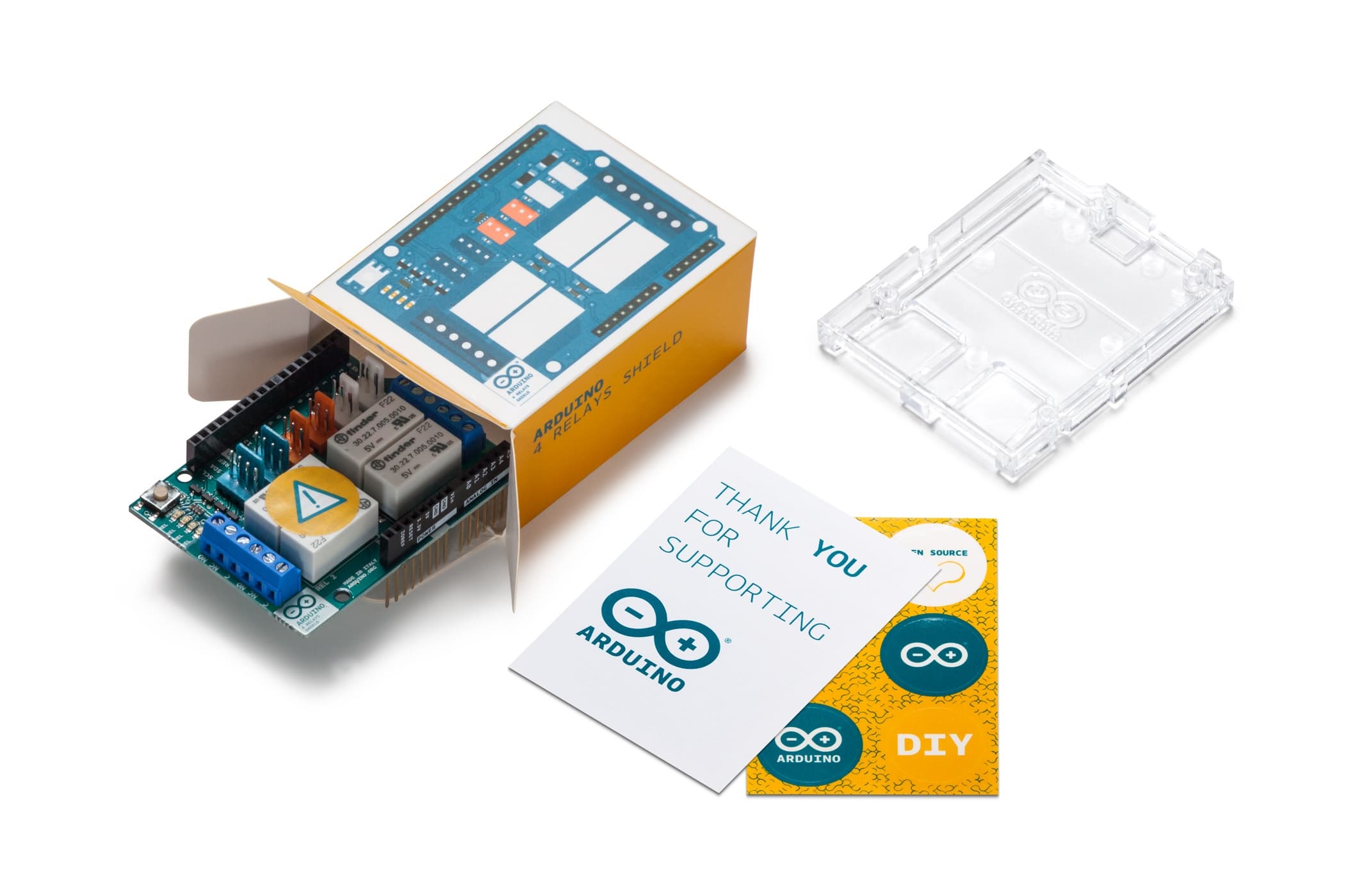
The Arduino 4 Relays Shield allows your Arduino driving high power loads.
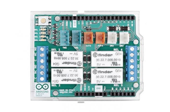
The Arduino 4 Relays Shield is a solution for driving high power loads that cannot be controlled by Arduino's digital IOs, due to the current and voltage limits of the controller. The Shield features four relays, each relay provides 2 pole changeover contacts (NO and NC); in order to increase the current limit of each output the 2 changeover contacts have been put in parallel. Four LEDs indicate the on/off state of each relay.
Getting Started
You can find in the Getting Started section all the information you need to configure your board, use the Arduino Software (IDE), and start tinker with coding and electronics..
Need Help?
- – On the Software on the Arduino Forum
- – On Projects on the Arduino Forum
- – On the Product itself through our Customer Support
Features
| Thinker Kit interface | 2x TWI, 2x OUT, 2x IN |
| Interfaces with Arduino Board | DIO |
| Relays | 4 (60W) |
General
| Operating Voltage | 5 V |
| Current needs | 140 mA (with all relays on, about 35 mA each) |
| PCB Size | 53 x 68.5 mm |
| Weight | 0.044 Kg |
| Product Code | A000110 |
OSH: Schematics
The Arduino 4 Relays Shield is open-source hardware! You can build your own board using the following files:
EAGLE FILES IN .ZIPSCHEMATICS IN .PDF
Description
| Operating Voltage | 5V |
| Coil current consumption | 140 mA (with all releays on, about 35 mA each) |
| Single pole chargeover contact maximum current | @ 30 V DC 2A |
| Maximum load voltage | 48 V |
| Maximum switching capacity | 60 W |
Power
The shield doesn’t need external power: it will be provided by the base board, through the 5V and 3.3V pins of the Arduino board used as base.
Input and Output
The relays are controlled by the following Arduino board pins: Relay 1 = Arduino pin 4 Relay 2 = Arduino pin 7 Relay 3 = Arduino pin 8 Relay 4 = Arduino pin 12 The shield features several TinkerKit input/output and communication interfaces. Connecting TinkerKit modules can simplify the creation of a project or a prototype. The on-board connectors are :
- – 2 TinkerKit Inputs: IN2 and IN3 (in white), these connectors are routed to the Arduino A2 and A3 analog input pins.
- – 2 TinkerKit Outputs: OUT5 and OUT6 (in orange), these connectors are routed to the Arduino PWM outputs on pins 5 and 6.
- – 2 TinkerKit TWI: these connectors (4-pin in white) are routed on the Arduino TWI interface. Both connect to the same TWI interface to allow you to create a chain of TWI devices.
Physical Characteristics
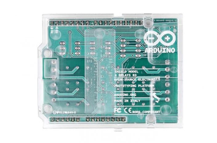
The maximum length and width of the 4 Relays Shield PCB are 2.7 and 2.1 inches respectively. Four screw holes allow the Shield to be attached to a surface or case. Note that the distance between digital pins 7 and 8 is 160 mil (0.16″), not an even multiple of the 100 mil spacing of the other pins.
Compatible Boards
The shield is compatible with all the Arduino boards, 5V and also 3.3V standards.
Санал болгох бараа
Үйлдвэрлэгч
Угсармал хавтан
- ЭХ ХАВТАН
- МЭДРЭГЧ модуль
- ХОЛБОЛТЫН модуль
- ИНТЕРФЕЙС хөврүүлэгч модуль
- МОТОР ДРАЙВЕР модуль
- ТЭЖЭЭЛИЙН модуль
- РЕЛЕ модуль
- Өргөтгөл модуль
- ТОВЧЛУУР модуль
- ӨСГӨГЧ, ДУУНЫ модуль
- ДЭЛГЭЦ, ЛЕД модуль
- Вольтметр, Амперметр
- RTC модуль
- AD/ DA модуль
- КАМЕР
- Програмчлагч хавтан
- EEPROM, I2C модуль
- Proto shield
- ИЖ БҮРДЭЛ
- Дагалдах хэрэгсэл
Зэс, универсал, сургалтын хавтан
- Зэс хавтан
- Универсал хавтан
- Сургалтын хавтан
Гэр ахуйн барааны хавтан
Лавлах утас: 77107805, 99198321
Хаяг : Улаанбаатар хот, Чингэлтэй дүүрэг, Компьютер ланд, 3-н давхар, 12 тоот
“ЧИП ЭЛЕКТРОНИКС” ХХК
© Copyright – 2025 www.chip.mn

