2.5-7.5V Adjustable Step-down Voltage Regulator
- үнэ: 27,000 төг
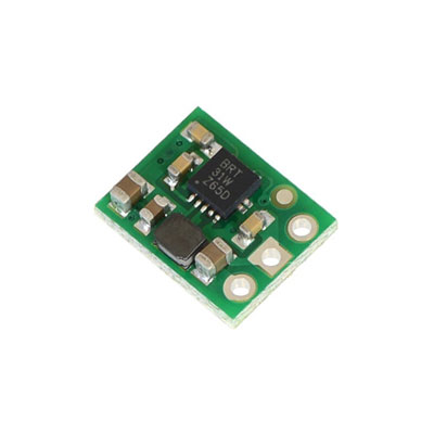
2.5-7.5V Adjustable Step-down Voltage Regulator D36V6ALV
Pololu item #: 3798
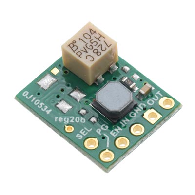
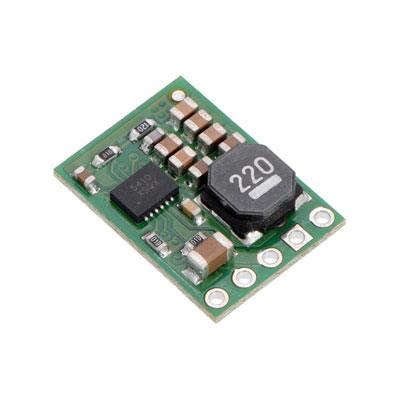
This compact (0.4″ × 0.5″) switching step-down (or buck) voltage regulator takes input voltages between 4 V and 50 V and efficiently reduces them to a lower, user-adjustable voltage set by an on-board trimmer potentiometer. It has an output voltage range of 2.5 V to 7.5 V and a maximum output current of 600 mA. It has a very low dropout, so it can be used with input voltages that are within a few hundred millivolts of its output. The pins have a 0.1″ spacing, making this board compatible with standard solderless breadboards and perfboards.
Dimensions
| Size: | 15 mm × 10 mm × 4 mm |
|---|---|
| Weight: | 0.6 g |
General specifications
| Minimum operating voltage: | 4 V |
|---|---|
| Maximum operating voltage: | 50 V |
| Maximum output current: | 600 mA |
| Minimum output voltage: | 2.5 V |
| Maximum output voltage: | 7.5 V |
| Reverse voltage protection?: | N |
| Maximum quiescent current: | 2 mA |
| Output type: | adjustable 2.5-7.5V |
Identifying markings
| PCB dev codes: | reg04a |
|---|---|
| Other PCB markings: | 0J3866 |
Details for item #3798
Features
- – Input voltage: 4 V to 50 V (input must exceed the output by the dropout voltage; see the dropout voltage section for details)
- – Output voltage: adjustable from 2.5 V to 7.5 V by on-board trimmer potentiometer
- – Maximum output current: 600 mA (see the maximum continuous output current graph below)
- – Fixed 2.1 MHz switching frequency
- – High-voltage enable input can put the board into a low-power state where it draws less than 2 μA (typical)
- – Low quiescent current: < 2 mA (see the quiescent current graph below)
- – Integrated over-temperature and over-current shutoff
- – Small size: 0.6″ × 0.4″ × 0.15″ (15 mm × 10 mm × 4 mm)
- – Weight: 0.6 g
Connections
This regulator has four connections: shutdown (SHDN), input voltage (VIN), ground (GND), and output voltage (VOUT).
The SHDN pin can be driven low (under 1.25 V) to turn off the output and put the board into a low-power state (< 2 μA typical). The regulator is enabled by default, and this input can be left disconnected if you do not need this feature.
The input voltage, VIN, powers the regulator and should be between 4 V and 50 V. If the input voltage gets too close to the output voltage, the output will start to drop, so you should ensure that VIN exceeds VOUT by at least the dropout voltage, which varies with the output voltage and the load (see below for graphs of the dropout voltage as a function of the load). Additionally, please be wary of destructive LC spikes (see below for more information).
The output voltage, VOUT, is determined by the trimmer potentiometer position, with clockwise turns increasing the output voltage. You can use a multimeter to measure the output as you set it. Please note that the output voltage can be affected by a screwdriver touching the potentiometer, so the output measurement should be done with nothing touching the potentiometer. When setting the output voltage, note that the buck regulator can only produce voltages lower than the input voltage. The following graph shows approximately how the potentiometer position maps to the output voltage settings on the D36V6ALV (blue curve) and D36V6AHV (red curve).
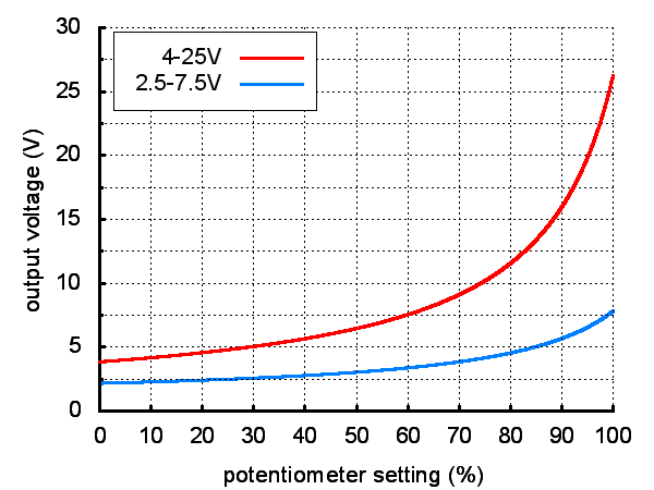 |
| Output voltage settings for the adjustable 2.5-7.5V and 4-25V buck regulators (D36V6Ax/D24V6Ax/D24V3Ax). |
|---|
The four connections are labeled on the back side of the PCB and are arranged with a 0.1″ spacing along the edge of the board for compatibility with solderless breadboards, connectors, and other prototyping arrangements that use a 0.1″ grid. You can solder wires directly to the board or solder in either the 4×1 straight male header strip or the 4×1 right-angle male header strip that is included.
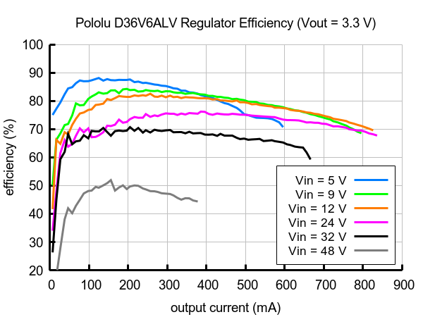
Typical efficiency
The efficiency of a voltage regulator, defined as (Power out)/(Power in), is an important measure of its performance, especially when battery life or heat are concerns.
 |
 |
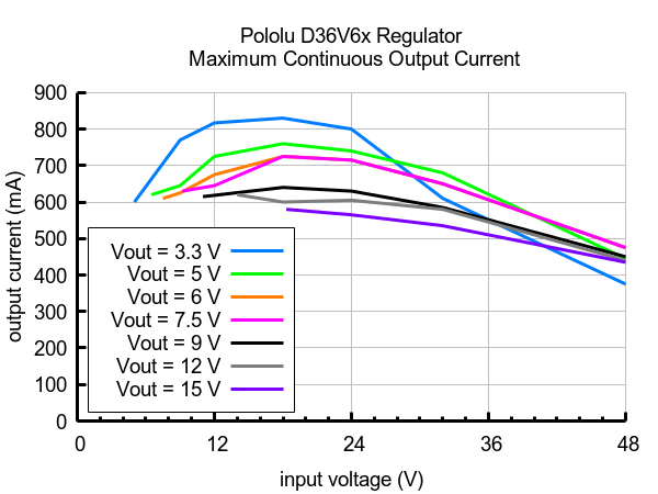
Maximum continuous output current
The maximum achievable output current of these regulators varies with the input voltage but also depends on other factors, including the ambient temperature, air flow, and heat sinking. The graph below shows maximum output currents that these regulators can deliver continuously at room temperature in still air and without additional heat sinking.
 |
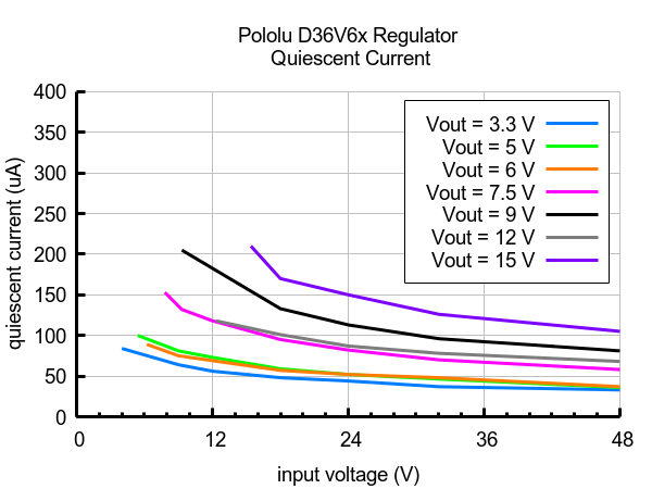
Quiescent current
The quiescent current is the current the regulator uses just to power itself, and the graph below shows this for the different regulator versions as a function of the input voltage. The module’s SHDN input can be driven low to put the board into a low-power state where it typically draws under 2 μA.
 |
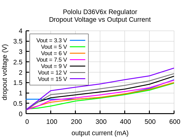
Typical dropout voltage
The dropout voltage of a step-down regulator is the minimum amount by which the input voltage must exceed the regulator’s target output voltage in order to ensure the target output can be achieved. For example, if a 5 V regulator has a 1 V dropout voltage, the input must be at least 6 V to ensure the output is the full 5 V. Generally speaking, the dropout voltage increases as the output current increases. The graph below shows the dropout voltages for the different members of this regulator family:
 |
LC voltage spikes
When connecting voltage to electronic circuits, the initial rush of current can cause voltage spikes that are much higher than the input voltage. If these spikes exceed the regulator’s maximum voltage (50 V), the regulator can be destroyed. In our tests with typical power leads (~30″ test clips), input voltages above 28 V caused spikes over 50 V.
If you are connecting more than 28 V or your power leads or supply has high inductance, we recommend soldering a suitably rated 33 μF or larger electrolytic capacitor close to the regulator between VIN and GND.
More information about LC spikes can be found in our application note, Understanding Destructive LC Voltage Spikes.