ZeroLAG Motor Driver Single 12V-32V x 40A

  • үнэ: 300,000 төг

Product Code: JS19332

Dimensions:

Size (cm): 8.1 x 8.1 x 3

Height (cm): 4

Weight (Kg): 0.05

The Most Advanced Motor Driver for Sumo Robots by JSUMO

ZeroLAG is our advanced motor driver for sumo robot projects. ZeroLAG Makes motor driving more precise and more importantly with zero delay.


Motor Driver can be controlled with any Microcontroller board like Arduino, ArduPro or Propic or mBed controllers. 

Logical design for sumo robot proects. Easy to control.


Designed by robot makers for robot makers, ZeroLAG is a compact single motor driver for sumo robots. It has current compensation with MOV, TVS and RC Snubber circuit. With built-in heatsink, it can drive motors up to 40A continuous and short duration current up to 80A.

ZeroLAG is perfectly companion for sumo robots, big explorer robots, Suv Robots.

  • – Operating voltage 12V-32V (3 Cell Lipo to 8 Cell Lipo)
  • – Operating temp. range: -20 °C ~ + 80 °C
  • – Max current 40A Continuous, 80A Burst.
  • – Supports DC motors, Suitable for Maxon RE32, RE35, RE40 and DCX35L Series.
  • – Supports Banebots motors up to 250 Watt.
  • – 81mm Length, 46mm Width and 29mm Height.
  • – Total 59 grams.

ZeroLAG Advantage vs Other Drivers

  • – Suitable for hard controlling like full reverse, full forward speeds without delays.
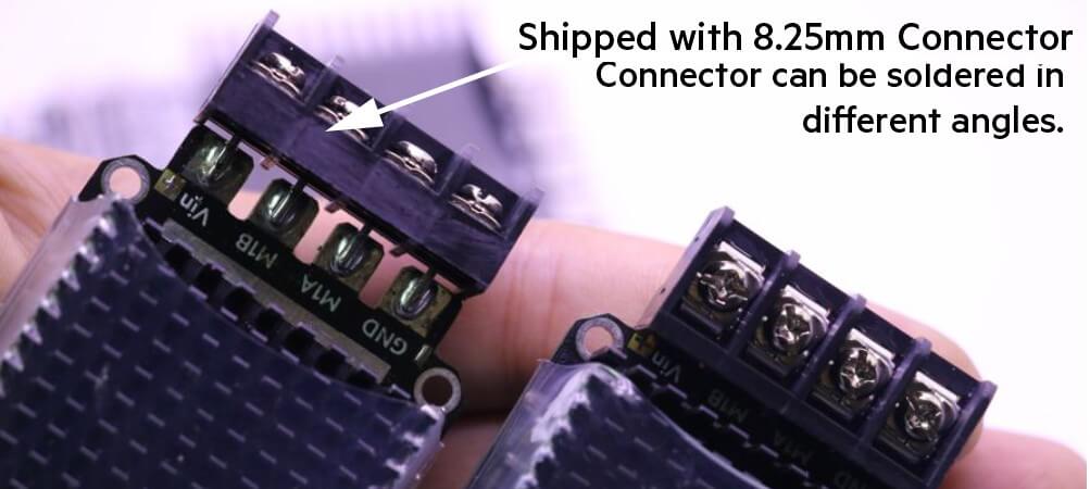
  • – Designed to be easy connect and develop. At Left side you connect to controller, and at right side you connect to motor and main power supply.
  • – Precision and professionalism in all stages of design, production and test.
  • – An affordable price.

How you can control ZeroLAG?

We used Phase Locked PWM control for ZeroLAG which gives better motor speed, better torque gradient for low speeds.
For driving motor with ZeroLAG, you need to use one PWM signal (For both direction and speed) and one Enable/Disable signal.
Also you need to attach both motor driver and main control circuit’s grounds together. It will make 0V reference point.
At ZeroLAG there is no MCU, which means there is no LAG, delay between motor control signals and motors.
PWM Pin: Controls both speed and direction. %50 duty cyle means %0 speed. %95 Duty Cycle full speed to forward, %5 Duty Cycle Full speed to backward. For controlling driver you need to supply PWM signals between %5 to %95 duty cycle (fullness value)
Disable Pin: This stops motors, When you apply Logic 1 (5V) it will stop motors.
For stopping motors there is 2 methods
1st you can apply %50 duty cycle PWM signal, that will stop motors. And 2nd is giving logic 1 to Disable signal. We strongly suggest you to use second disable pin option. Giving %50 signal to motor driver will result temperature increase of mosfets.
We are shipping with 8.25mm Pitch semi closed barrier connector terminal. That strong terminals can be soldered in various positions like that image at upside.

How to Control ZeroLAG with Arduino?

Easy!
First of all we need to modfiy Arduino’s base PWM frequency. That frequency normally 490hz which is enough for controlling led brightness but not enough for controlling motor speed. With special timer configuration function we change frequency from 490 hz to 3.9 khz.

This code gives 2 Second Forward, 1 second stop and 2 Second Backward turning routine.

int EN=3; // Enable Pin Connected to Digital 3
int Speed=9; // Motor Speed & Direction Pin Connected to Digital 11void setup() {
pinMode(EN, OUTPUT); // Enable Pin Made Output
Serial.begin(9600); // Serial Iterface Started at 9600 bps baudrate.
digitalWrite(EN,LOW); // Enable Pin set low for avoding false startups.
delay(1500); // Delay for 1.5 Second.
setPwmFrequency(9, 8); // Set Pin 9’s Pwm Frequency tp 3906 hz (3.9 Khz)
}

////////// PWM Frequency Modify Function////////////////
void setPwmFrequency(int pin, int divisor) {
byte mode;
if(pin == 5 || pin == 6 || pin == 9 || pin == 10) {
switch(divisor) {
case 1: mode = 0x01; break;
case 8: mode = 0x02; break;
case 64: mode = 0x03; break;
case 256: mode = 0x04; break;
case 1024: mode = 0x05; break;
default: return;
}
if(pin == 5 || pin == 6) {
TCCR0B = TCCR0B & 0b11111000 | mode;
} else {
TCCR1B = TCCR1B & 0b11111000 | mode;
}
}
}

void loop() {
Serial.println(“FULL FORWARD”); // This Serial Prints sent to Computer Screen to Arduino’s Serial Monitor.
digitalWrite(EN,HIGH);
analogWrite(Speed, 252); // Full FWD Speed (252/255)
delay(2000); // 2 Second Delay

Serial.println(“STOPPED”);
digitalWrite(EN,LOW);
analogWrite(Speed, 128); // Half Duty Cycle and Enable Low Stops Motor (128/255)
delay(1000);

Serial.println(“FULL BACKWARD”);
digitalWrite(EN,HIGH);
analogWrite(Speed, 2); // Full BWD Speed (2/255)
delay(2000); // 2 Second Delay

Serial.println(“STOPPED”);
digitalWrite(EN,LOW);
analogWrite(Speed, 128); // Half Duty Cycle and Enable Low Stops Motor (128/255)
delay(1000);
}

Caution! There is no current limiter at ZeroLAG also there is no reverse battery protection. Please use and attach carefully. (Which means don’t make short circuit or reverse attach battery)

Санал болгох бараа